electronics production
fab academy week 4
This week was about electronics production (class content here). We learnt about the materials used to create PCBs (Printed Circuit Boards), the different types of PCBs with one or multiple layers and the fabrication techniques. For the material, in the fab lab we use FR1 which is paper based and has also resin because it is more natural, low cost and easy to make single layer PCBs.
cutting
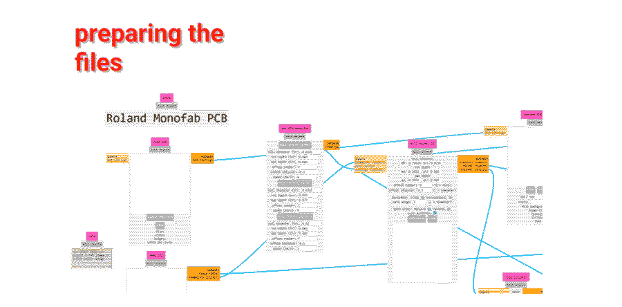
To fabricate the PCB we use a milling machine, the one we have at Fab Lab BCN is Roland MonoFab SRM-20. The file has to be prepared before in a software developped by MIT, modsproject and the outputs are 2 files : one for the traces and one for the outline.I know it is not supposed to be the highlight of this class but I really like the interface and non conventional navigation on modsproject.
soldering
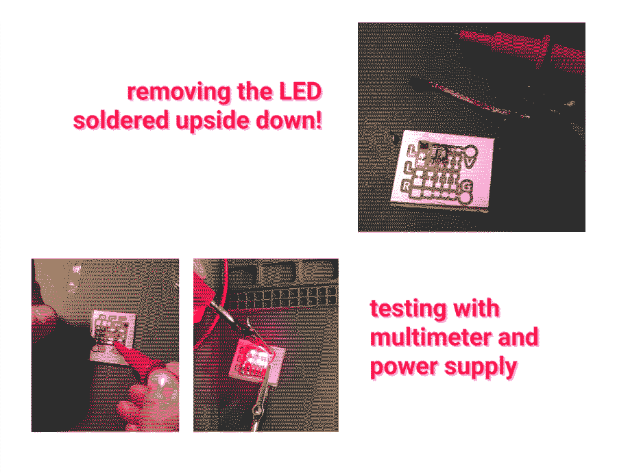
The soldering part reminded me the technology classes in secondary school I remember I enjoyed it a lot. I think at that time I could do perfect solderings of LEDs so I lost this skill now! In the class content there is a great vintage video that explains how to make good solderings I find. I soldered led and resistors on one of the PCB that were already fabricated.mistakes I made:
- I soldered one LED in the wrong side because I forgot they had a negative side. So I need to remember that a green line or a dot are always indicating the side negative (connected to ground)
- I tried to remove the LED using a copper wire to remove the solder but it broke the trace. It is better to first remove the element just by melting the solder with the tip of the iron and use the copper only after, on a flat board to remove excess of solder.
Compared with the previous weeks where we could directly have a tangible result, here Electronics production is more like a step amongst others in the process of making an electronic object later. Actually I am wondering why we didn’t do electronics design before so we could have cut the board we designed.
tools I worked with
Ironsolder
multimeter
power supply
learnings
- Inverting the colors in mods to be sure we are keeping the black part
- Offsetting to remove copper around the trace only to save time on the machine
- Green line or a dot on an LED are always indicating the side negative (connected to ground)
- To remove an element soldered on a PCB, first remove the element just by melting the solder with the tip of the iron and use the copper only after, on a flat board to remove excess of solder