computer-controlled machining
fab academy week 7
This week we focused on another computer controlled machining technique : CNC Milling which is a substracting procedure (class content here). We often just refer to it as “CNC” but CNC stands for Computer Numerical Control so actually laser cutting is also CNC.
The important steps in this process are : designing for machining, preparing the file for cutting and cutting. We started with 2D-2,5D designs and it already enables us to create furniture. It is quite satisfying to be able to make something that is “human sized”!
designing for machining
Before starting, I know I am not using the right words so from today, I will try to learn the exact words of wood joinery so I can stop saying “holes” and “piece of wood”. So in my case, I used “through tenon and mortise” joints. Mortise being the rectangle hole and tenon the tongueA lot of much cooler joints can be seen here for example here (downloadable digital joints for woodworkong) or here (traditional Japanese wood joinery)
To pursue on my low tech explorations, I decided to make a “fireless cooker” stool. Fireless cooking is a cooking method that requires a small amount of energy. Pots are heated on a stove until boiling point and then put in an isolated box to continue cooking without further energy input. Though, having an extra box for it can be annoying in a kitchen so including it in a stool could be a nicer way to bring it to my kitchen.
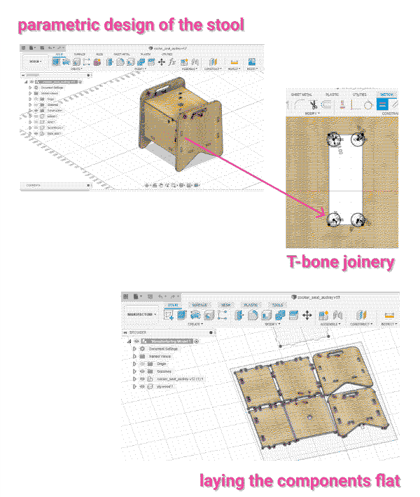
I used Fusion 360 and parametric functionnalities to design the stool. I started with the main box size that can change if we want to design it for smaller pots. But I did it so it could fit the biggest cooking pot I have.
source The Joinery
joinery - T-bone, dog-bone, Mickey Mouse
Because of the thickness of the endmill, we cannot have 90° angles in the design. So to make sure the joints fit well, I needed to modify their shape with either T-bone or dog-bone or mickey mouse shapes. I followed this tutorial to make T-bones in my joints.
kerf
The kerf is the tool diameter but we can specify in the cutting settings if we want to cut inside, outside or on the vector. Even though, there is a tolerance of about 0.25mm because the material is pushed by the endmill and bouncess back a little bit. So the design needs to be bigger : for the joints to fit, I can either make the tenons a bit bigger or the mortise a bit smaller.
In my case, I had to do it in a second step in Rhino with and offset of 0.25mm for tenons because the way I designed the joints in Fusion didn’t allow me to do it there.
The way I did it was: I designed the tenons first, and then used the “combine” functionnality to create the mortise holes is the other components. This works well but the consequence is that the tenons and mortise shapes are connected. So if I add a tolerance to the tenons, it changes the mortises size at the same time. So an alternative would be to draw the holes instead.
When the design is ready, I export it to prepare the cutting settings in a different program. I first layed all the components flat in Fusion by going to the “Manufacturing” menu and use the “Arrange” feature to automatically lay them flat. This video can help to do it. From there, create a new project and export the sketch in dxf.
preparing the file for cutting
I opened the dxf file in Rhino to create different layers (this can also be done in Inkscape) and associate a color to each layer : blue for the outside cuts, and red for the inside (holes and pockets). Each layer is for a different cut.An easy program for the cutting settings is Easel but here we used Rhino Cam that we have at the fab lab. For each layer, we setup different functionnalities including:
- spindle speed: here 18000 RPM (revolution per minute)
- chip load : this can be found on the datasheet of the endmill and depends on the material we cut
- feed rate is the cutting speed and can be calculated with a formula : chip load * flutes * RPM = 0.294*1*18000 = 5292 mm/min (values we used during the class)
- cut depth : the maximum is half of the endmill diameter so 3mm here
- cut path : inside, outside or on the line
- options for holes : normal cut if we added tabs or screws, pocketing for smaller holes
Note: the zero is on top of the material (top left corner of the box defined on Rhino Cam)
The material will need to be screwed on the sacrificial board for it not to move during the cutting. A tip for the design is to plan in advance where the screws are going to be. We then have a layer just for the screws and we set up engraving their location in a separate file.
cutting
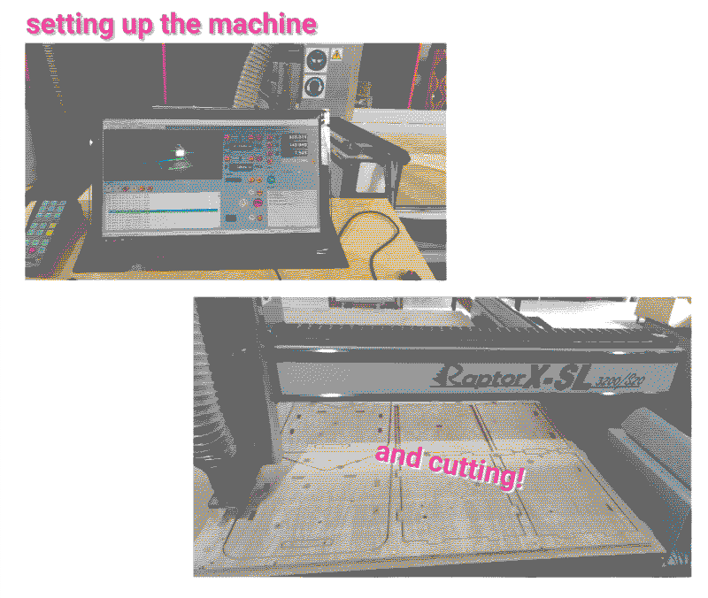
I followed these steps:- Place the material aligned to the left down corner
- Pick the right end mill, here we prepared a file for a 6mm down mill.
- Pick the collet for 6mm mills and clean it
- Attach the collet to the machine, place the end mill and tighten with the tools
- Open the program that goes with the machine here KinectiC-NC
- In "Jog/Setup" move the X and y to the origin point - when they are at the right position press zero to set them to these coordinates. Then use the magnetic tool to setup the z
- Put on protection! (Eyes and ears)
- Turn on the air aspiration
- In "Program", open the first g-code file for the screws and run it
- After the screw locations are engraved, move the end mill away from the material and place the screws
- Apply force and make sure to have the electric screwdriver aligned with the screw! For each screw, unscrew and screw again to make sure the material is flat on the base
- Setup the z again because it might have changed now that the mating is screwed
- In Program, open the g-code file for the cut and run it
assembling
Remove the pieces from the board, unscrew the material, sand the pieces and assemble!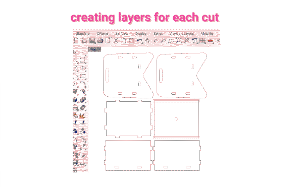

tools I worked with
Fusion 360Rhino
Rhino Cam
Raptor x-SL 3200/S20
learnings
- Design the joints so kerf tolerance can be added in an easier way.
- Plan in advance where the screws will be.
- Make sure that all the components are in the same plan! If not, use “make 2D” command.