embedded programming - input & output devices
fab academy weeks 8, 10 & 13
In this page, I will combine the tasks of the three following classes: embedded programming (class content here), input devices (class content here) and output devices (class content here).
For week 6 "Electronic design", I milled a PCB to make a thermometer with 2 input components which will be NTC thermistors, one for the outside temperature and one for inside (meaning inside a solar oven or fireless cooker for example). I had detailled the steps of the prototyping on breadboard and milling in week 6 page here.
soldering
I soldered the different components needed for my PCB: RGB LEDs, resistors, NTC thermistor and pin outs for the second NTC thermistor.Before soldering I checked the datasheets of the components to know what resistors I had to add and also the side of the soldering.
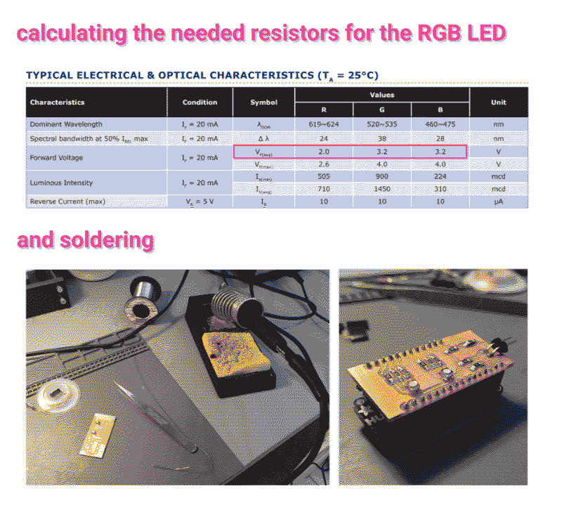
In the RGB LED datasheet, I searched for the “Typical electrical and optical characteristics” on the datasheet and looked for each LED the Forward Voltage line and take the Voltage average of each LED to calculate the resistor you need with Ohm’s law (R=V/I).
In my case, the cicuit will be powered by 3.3V and these LED need an intensity of 20mA.
- For RED LED: It uses in average 2V so the resistor will need to “absorb” 1.3V. We need a resistor of R=V/I = 1.3/0.02= 65 ohms minimum. I can use a 100 ohms resistor.
- For BLUE and GREEN LEDs: They use in average 3.2V so the resistor will need to “absorb” just 0.1V. We need a resistor of R=V/I = 0.1/0.02= 5 ohms minimum. I can use a 10 ohms resistor.
testing and... fixing
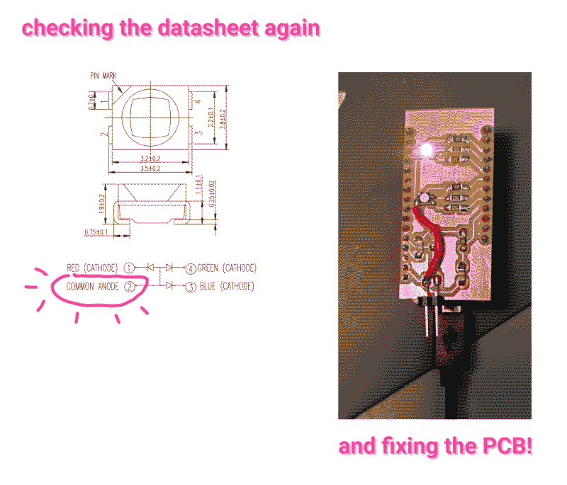
After soldering, I connected the new PCB to try with the program I had prepared on Arduino IDE. I was able to read the temperature but the RGB LEDs didn’t light up. After investigating with Josep and going through the RGB datasheet, we found out that it was wrongly connected.The RGB LED has 4 connections: red LED, green LED, blue LED and the fourth one, according to the datasheet is “Common anode” so it should be connected to power. However, I design my PCB based on the prototype I did on a breadboard with the RGB LED component I had in the kit. The component in the kit, like a lot of RGB LED components had to be connected to ground!
So my PCB was wrong and to fix the issue, I had to remove the connection between the fourth leg of the RGB LED and ground and solder a wire to connect it to the VCC. It looks a bit bad but now it works! I can now control the color of the LED based on the temperature of the NTC thermistor (for the outside temperature) and I will add another NTC connected to the pin outs and a cable so it can go in the solar oven.
tools I worked with
Arduino IDEBreadboard, NTC thermistor, RGB LEDs, resistors, PCB
Soldering station, multimeter